Avance Intel Modular Server Guide
Last Modified: 08/29/2012 at 19:42 | Release:Table of Contents
Network Configuration Examples
Avance installation with a single business network
Avance installation with multiple business networks
Avance installation with split-site configuration
Multiple Avance nodes in the same chassis
Important Storage Considerations:
Theory of Operation
On an Intel Modular Server (IMS) system, multiple Compute Modules share common hardware components. These components are managed by IMS itself and information about them is not readily available at the operating system level on a Compute Module; therefore, Avance does not validate, monitor or control certain chassis components and events. Predictive failover of VMs will not occur when these components fail. Avance administrators using the Intel Modular Server should use the mechanisms provided by Intel (such as SNMP and e-mail notifications) to monitor the hardware components described in the following sections in order to provide a high-availability environment.
Storage
Avance cannot determine the RAID configuration of the disks on an Intel Modular Server system and does not have access to physical disk state information. Because of this, disk failures will not be recognized by Avance until they reach the logical disk level. Stratus recommends the storage devices be RAID-protected to avoid data loss in case of a physical disk failure.
Network
Intel Modular Server does not allow the built-in network ports of a Compute Module to connect to two different switch modules of the same chassis. To work around this limitation and to eliminate a single point of failure, Avance requires that an add-in Mezzanine card be installed for each Compute Module and that the Intel Modular Server contain two Switch Modules in each chassis. Also note that as of this writing, IMS does not support high-speed 10G network cards; therefore, Avance is not able to provide support for those cards on the private link between nodes.
Chassis and Power
On Intel Modular Server Avance cannot power-on its peer node. If an administrator is required to perform a power-on action, a request will be made via an alert in the Avance portal. In most cases, Avance will be able to shut down the peer node when necessary; when it cannot, manual intervention is required and the administrator will be notified.
Avance UPS configuration feature is not available on Intel Modular Server. Stratus recommends that the separate power supplies on the IMS chassis be connected to different power sources to prevent node failure in the case of a power interruption on one of the sources.
Hardware Requirements
In order to install Avance on Intel Modular Server, the following hardware requirements must be met. More details about these requirements can be found later in this document. Refer to the Avance Compatibility Matrix for the list of supported chassis and modules.
- An Avance unit consists of two nodes, each of which is a Compute Module in a separate Intel Modular Server chassis
- A network mezzanine card must be installed in each compute module on which an Avance node resides
- Avance requires two Gigabit Ethernet Switch Modules installed in each Intel Modular Server chassis
- Only one Storage Controller Module can be installed in each chassis
- Each node on an Avance unit must contain at least two logical disks
- A chassis may contain more than one node from different Avance installations
Network Configuration Examples
Avance installation with a single business network
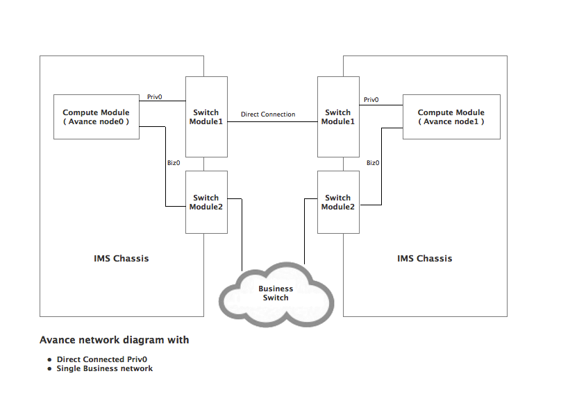
The following example uses a direct private link (priv0) (on the first switch module (SWM1)) to communicate between node0 and node1. Since Avance heartbeats with its peer node only on priv0 and biz0 (network0) networks, the IMS servers must be configured such that priv0 and biz0 are on two separate Switch Modules as described in the following steps.
Configuration Steps:
- Reset the Compute Module to the factory defaults
Configuring Switch Module 1:
- Select Switch Module 1 (SWM1) from the IMS administration console and click on “Configure Ports”
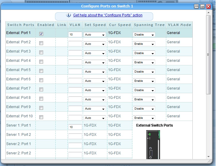
- Configure server port 1 of the compute module to use a unique VLAN as shown in the following diagram.
- Disable “Spanning Tree” on this port.
The following picture shows “Server 1: Port 1″ and “External: Port 1″ configured to use VLAN 10
- Disable 10Gb X-Connect

- Click Apply to save the changes
- Ensure External Port 1 from the first IMS chassis is connected directly to the External Port 1 of the second chassis.
Note: You need to perform the above steps on Switch Module 1 on both IMS chassis.
Configuring Switch Module 2:
- Select Switch Module 2 (SWM2) from the IMS administration console and click on “Configure Ports” menu.
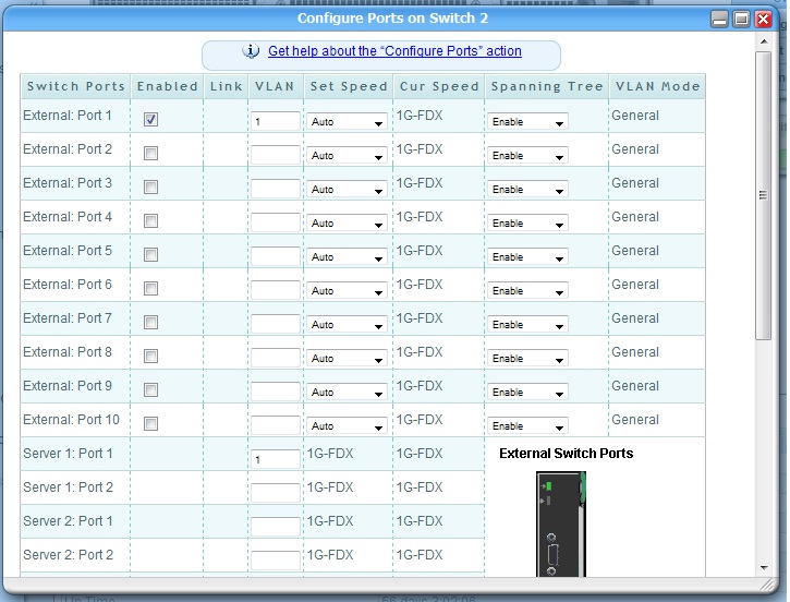
- Configure server port 1 of the compute module to use a different VLAN than the one used by priv0
- Enable “Spanning Tree” on this port
The following picture shows “Server 1: Port 1″ and “External: Port 1″ configured to use VLAN 1
- Disable 10Gb X-Connect

- Click Apply to save the changes.
Note: You need to perform the above steps on Switch Module 2 of both IMS chassis.
Avance installation with multiple business networks
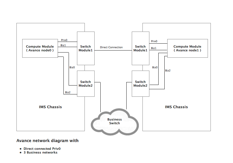
The following example uses a direct private link (priv0) to communicate between node0 and node1 of the Avance unit. Avance allows up to three business networks to be configured on the IMS systems. Since Avance heartbeats with its peer node only on the priv0 and the biz0 networks, IMS must be configured such that the priv0 and ibiz0 are on two separate Switch Modules to prevent a single point of failure.
Configuration Steps:
- Reset the Compute Module to the factory defaults
Configuring Switch Module 1:
- Select Switch Module 1 (SWM1) from the IMS administration console and click on “Configure Ports”
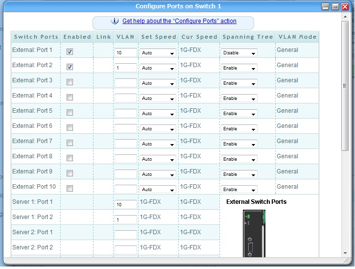
- Configure server port 1 of the compute module to use a unique VLAN as shown in the following diagram.
- Disable “Spanning Tree” for Server 1 Port 1.
- Configure server port2 of the compute module to use a VLAN number that’s different from that of Server Port 1. This port will be used for your business communication. Based on your needs, you may choose to configure all business networks on the same VLAN or on different VLANs.
- Enable “Spanning Tree” for all business network ports
The following picture shows priv0 configured on unique VLANs and the business networks configured to use VLAN 1.
- Disable 10Gb X-Connect

- Click Apply to save the changes.
- Ensure External Port 1 from the first chassis is connected directly to External Port 1 of the second chassis.
Note: Perform this configuration on Switch Module1 of both chassis
Configuring Switch Module 2:
- Select Switch Module 2 (SWM2) from the IMS administration console and click on “Configure Ports” menu.
- Configure the server ports of the compute module to use a different VLAN than that of Server 1 Port 1 of Switch Module 1 (which is priv0). You may choose to configure all your business networks on the same VLAN.
- Enable “Spanning Tree” for both of the ports.
The following picture shows business networks from all Avance units configured to use VLAN 1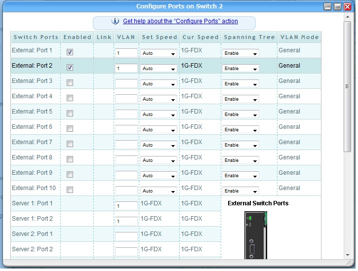
- Disable 10Gb X-Connect

- Click Apply to save the changes.
Note: Perform this configuration on Switch Module2 of both chassis
Avance installation with split-site configuration
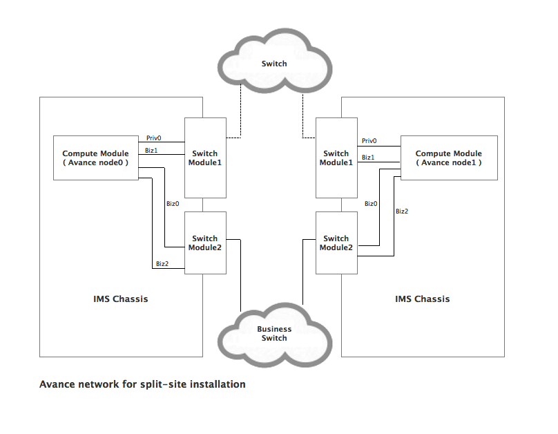
Configuring Avance for split-site is identical to configuring Avance in our first two examples except that the priv0 link can be connected via a separate redundant network switch. To avoid single points of failure, do not connect your business networks and the priv0 networks using the same network switch. For additional information on Avance Split Site configuration refer to the Avance split-site configuration document.
Multiple Avance nodes in the same chassis
A single chassis may contain more than one Avance node from different Avance units. Configuring two nodes of the same Avance unit in the same chassis is not a valid Avance Configuration. Depending on whether you intend to configure single or multiple business networks and whether you want to configure a direct link or a split site configuration, follow the steps outlined above for each Avance Unit.
Note: The priv0 network for each Avance unit must be configured on a unique VLAN for every Avance configuration in the chassis.
Storage Configuration
The physical drives in an Intel Modular Server are grouped into storage pools. The administrator carves virtual drives out of these storage pools and assigns virtual drives to modules. Each virtual drive can only be assigned to one module as shown in the following block diagram.

Important Storage Considerations:
- Each virtual drive is seen by Avance as a logical disk. In order to maintain availability, it is required that each node in an Avance unit be assigned at least two logical disks to be used as boot drives; it is recommended that each of these disks come from a different storage pool.
- When creating a virtual drive from a storage pool using the Intel Modular Server Control utility, you assign it a drive number (also known as a LUN). Intel Modular Server requires that the boot device be Drive 0. In addition, Avance requires that you assign a second logical disk (LUN 1). This disk is used as a secondary system disk in case of a catastrophic failure of the boot device, allowing Avance to migrate VMs running on the affected node to the peer node. Stratus recommends that the system disks be RAID-protected to avoid data loss in case of a physical disk failure.
- None of the boot drives can be of a size greater that 2.2 TB.
Steps to configure Storage:
Create a Storage Pool:
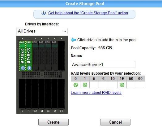
- Click on the Storage tab in the IMS console and click “Create Storage Pool”
- Select the Physical Drives you want to include in this Storage Pool by clicking on them
- Give a name to the Storage Pool
- Click Create
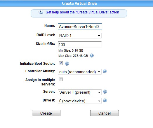
Create a Virtual Drive
- Click on the Storage Pool and then click on Create Virtual Drive
- Give a name to the Virtual Drive
- Select the appropriate RAID Level
- Check Initialize Boot Sector
- Set Controller Affinity to auto
- Select the server you want to assign this drive to from the drop down box
- Select the Drive number of the drive. Note that drive 0 is always the boot drive of the system
Recommendations and Trouble Shooting
- Avance is unable to determine the RAID configuration of the disks on Intel Modular Server and does not have access to physical disk state information. Because of this, disk failures will not be recognized by Avance until they reach the logical disk level. Avance administrators using Intel Modular Server should use the mechanisms provided by Intel (such as SNMP and e-mail notifications) to monitor physical disk issues.
- In the event that a boot device fails, the node will not be able to reboot directly from the secondary system disk because of the Intel Modular Server restriction that only LUN 0 can be used as a boot device. However, after disk replacement, the node can be recovered via the ‘Recover’ operation in the Physical Machines page.
- Intel Modular Server allows two Storage Modules to be installed in a Modular Server chassis. Avance will not install or function properly if two Storage Modules are used, therefore, Stratus requires that only one Storage Module can be installed in a Modular Server chassis.
Installation Steps
Avance can be installed on Intel Modular Server via two methods: by DVD or remotely using KVM. Before beginning either method, you must first configure your network and storage as described in the sections above.
DVD Installation
Each Compute Module of the Intel Modular Server has a USB port to which a DVD drive can be connected. In order to install Avance, the following steps must be taken:
- Connect a DVD drive containing an Avance Install DVD to the module that is going to be node0 for your Avance unit.
- From the Intel Modular Server Control utility, connect using Remote KVM for this module.
- From the Intel Modular Server Control utility, power on the module.
- At the KVM console, select the DVD drive as your boot device.
- Proceed through the rest of the installation, following the steps in the Avance Installation Guide.
Remote Installation via KVM
- Copy your Avance Install ISO onto a local machine (i.e., the machine on which you are running a browser).
- From the Intel Modular Server Control utility, select the module which is going to be node0 of your Avance unit and select “Remote KVM & CD” (you may need to select “Terminate KVM Session” first if another user has launched a KVM session for that module).
- In the new window that appears, click on “Device”, select “Redirect ISO” and navigate to the ISO.
- From the Intel Modular Server Control utility, power off and then power on your module.
- At the remote serial console, select the DVD drive as your boot device.
- Proceed through the rest of the installation, following the steps in the Avance Installation Guide.
Conformance Tests
Once Avance has been installed and configured, it is recommended that a series of conformance tests be performed to verify that Avance is configured properly.
Basic migration
This test verifies that basic migration of a VM is working properly.
- After Avance is installed, create a VM.
- Log on to the VM. If it is a Windows VM, run the Task Manager and select the Performance tab. If it is a Linux VM, start the ‘top’ utility. You’ll want to be able to monitor the output of the Task Manager or ‘top’ while executing the rest of the test.
- Determine on which node the VM is running (this can be seen on the Physical Machines page by selecting the VM tab for each node). Put that node into maintenance mode by selecting ‘Work On.’
- The VM should now migrate to the other node. While it is migrating, make sure it does not reboot by monitoring Task Manager or ‘top’.
- When migration is complete, you can take the node out of maintenance by selecting ‘Finalize.’
Disk fault
NOTE: Do not perform this test unless each logical disk you have created as a system disk is each in its own unique storage pool. Otherwise, removing the physical drives could adversely affect other modules in your IMS system.
- After Avance is installed, create a VM.
- Log on to the VM. If it is a Windows VM, run the Task Manager and select the Performance tab. If it is a Linux VM, start the ‘top’ utility. You’ll want to be able to monitor the output of the Task Manager or ‘top’ while executing the rest of the test.
- Determine on which node the VM is running (this can be seen on the Physical Machines page by selecting the VM tab for each node).
- Assuming that you have created two logical disks, create a logical disk failure on the second logical disk on the node on which the VM is running by removing the physical drives in the logical disk’s storage pool. For RAID-1 and RAID-5 logical disks, this means removing two physical drives.
- The logical disk failure will cause the VM to migrate to the other node; after migration, the node with the disk failure will reboot.
- After the node has rebooted, correct the disk failure by re-inserting the disks. Reboot the node by placing it into maintenance mode (by selecting ‘Work On’ on the Physical Machines page) and the selecting ‘Reboot’.
- Once the node has rebooted, take it out of maintenance mode by selecting ‘Finalize’ on the Physical Machines page.
- Select the ‘Disks’ tab for the node on the Physical Machines page. In the ‘Action’ column, select ‘Activate Disk’ for the logical disk that has failed.
- After some period of time, the logical disk will return to a healthy status (signified by a green check mark).
Network fault
- After Avance is installed, create a VM.
- Log on to the VM. If it is a Windows VM, run the Task Manager and select the Performance tab. If it is a Linux VM, start the ‘top’ utility. You’ll want to be able to monitor the output of the Task Manager or ‘top’ while executing the rest of the test.
- Determine on which node the VM is running (this can be seen on the Physical Machines page by selecting the VM tab for each node). If it is not running on the primary node, force it to migrate to the primary by putting the secondary node into maintenance mode (by selecting ‘Work On’); once the VM migrates, bring the secondary node back into service by selecting ‘Finalize.’
- Remove the network cable from the external port representing priv0 on the primary node. This should cause the secondary node to shut down and to generate a lost communication alert.
- Plug the cable back in. Power off and on the secondary node from the IMS console. The alert should clear once the node has booted. If you have configured a unique VLAN for your ibiz0 network, remove the network cables on the external ports on the primary associated with that VLAN. The VM should migrate to the other node and a ‘network miswired’ alert be generated. When you re-insert the network cables, the alert will clear.

